Martin Huml, OL5Y/OK1FUA,
During my radio amateur activities, I dedicate most of my time (probably like any one of us) to the question of antennas. And one of the most important and maybe the most challenging task is to get the antenna “into the air” and keep it there. Apparently this applies to all antennas, perhaps with the exception of beverage antennas... I wrote about this subject in the article “How to build and guy simple antenna masts” (magazine “Radioamatér” 2 & 3/2004). At that time, I already felt that this issue is so interesting, complicated and extensive that it would be appropriate to return to it.
Another motive for writing the following article was to include the questions asked either by my friends or emerging on their own, e.g. “Why are you guying the vertical so low down?”, “Will this rope be strong enough?”, “Will this mast be able to carry the antenna?” and so forth. Most of the time I couldn't find a better answer than “because I think it's enough” or “because I saw it somewhere like that”. This doesn't sound very scientific. Practice and experience are great and irreplaceable, but too much of it is guesswork, so when my activities brought me to “guying” I decided to look into it from the theoretical perspective as well. First, I would like to state that I am not an engineer; so, after studying some time, I consulted Engineer Richard Beber, who, unlike me, has studied this issue. Here, I would like to thank him - the article wouldn't have been written if it weren't for him.
Hence, as indicated by the name of this article, its main subject is focused on how to guy the antennas. This doesn't mean that owners of the self-standing masts won't find something interesting. For instance, calculations of forces acting on the antenna in the wind or other matters might be useful.
Used terms and simplification
I ask the experts and linguists for leniency - I use these terms as I know them from amateur practice:
- Place (point) of mounting = the place where the guy rope is mounted (attached) on the mast
- Height of mounting = the distance between the point of mounting and the mast bottom (base, labeled HKI)
- Groung anchor point (Guying point) = the place where the guy rope is attached to the ground (or other fixed point)
- Distance of guying = the distance between the guying point and the mast bottom (base, labeled RKI)
- The system = the mast with antenna
A vertical antenna is actually a mast without the antenna. Therefore, where it is not appropriate in the following text, I will not distinguish between these two types of antennas. In other words, e.g. the phrase “guying in the middle of the mast” will have to be understood as “guying in the middle of the vertical”.
Unless stated otherwise, we assume that the mast is built on a horizontal surface; therefore, the ground guying points and the mast bottom are at the same level, perpendicular to the axis of the mast. This is for simplicity - the reality definitely tends to be different. Therefore, the following text will indicate how to deal with the reality.
In our considerations, we also do not deal with the behaviour of the antenna itself - we assume that the antenna on the mast does not change.
And, finally, for those who are not friends with physics - we will talk a lot about force, whose unit is 1 N (Newton). For instance, if you lift a weight of 1 kg, the acting force on you is approximately 10N.
The Antenna and the Mast
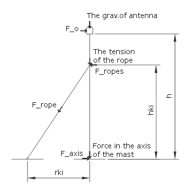
If we look at the simplified model of the guyed mast and the antenna at its top (fig. 1), the following forces will affect the system:
- gravity force (mass of the mast, ropes and antennas),
- resistant wind force,
- tension force of the guy ropes.
This set of forces will produce a reaction so that the resulting forces will be balanced. The reaction will appear in the gripping of the mast bottom and in the places of mounting of the guy ropes. There will also be a flexible deformation of the mast and the ropes. In this respect, we do not consider the irreversible deformation or destruction of the material - it is these cases that we want to avoid and therefore we will focus on the identification of all acting forces.
But forces do not represent all factors that will influence the behaviour of the system. We must not forget about the structure of the mast (tube, lattice structure etc.) and the material of which it is made, especially its physical properties such as density (specific gravity), flexibility and strength. Similarly, we need to know the properties of the guy ropes - their strength and elongation. Let's summarise what we need to know:
- antenna - mass
- antenna - shape (number, length and diameter elements)
- mast - structure, material
- guy rope - elongation (stretch at working load), strength
And the parameters with which we will be dealing are as follows:
- total height (the height of the antenna above ground = the height of the mast)
- the number of the guying directions (3 or 4)
- the number of guying levels (at how many levels will the mast be guyed)
- the height of the guy rope mounting(s)
- the distance of the guying point from the base
The distance of the guying
The first question that we will address is the influence of the distance of guying on the size of the forces (acting on the mast and the guy ropes). We will divide this task into the following marginal situations - in the first case, the wind is blowing from the guying direction; in the second case, the wind is blowing “in between the guys”. (fig. 2)
If the wind is blowing from the point of guying direction, it is a simple composition of forces - the case of a right triangle where one of the legs is the mast (h), the second one the distance between the mast bottom and the point of guying (r), where the guy rope is the hypotenuse (l). The proportion in which the individual legs of this triangle are is the proportion of forces acting in individual directions. We know (can calculate) the force Fant caused by the wind acting on the antenna. (Its specific value is not important at this moment; we will deal with it later - as we are now assessing the influence of the distance of the point of guying.) So the force on the mast (in its axis) is Fst = Fant * h / r, and the force acting on the guy rope is Fko = Fant * l / r. We will calculate the length of the rope by the Pythagorean Theorem: l = √(h2 + r2).
When the wind is blowing from the direction of the axis between the guys the situation is somewhat more complicated, because we have to bear in mind the angle between the guys - in other words, to how many directions the mast is guyed.
Guying directions
For this purpose we look at the mast from the top and introduce a total of 3 points - the mast and 2 guying points. Further we will introduce the direction from which the wind is blowing - it is the axis between the guying points going through the mast. The place where this axis intersects the connecting line between both of our guying points is a point that represents the virtual guying point for the calculation of acting forces. We see that it is much closer to the mast bottom than the guying distance - the closer it is, the larger the angle between the guys.
This is again a case of triangles, but not necessarily right angle triangles. If we apply the basic goniometric functions we get to these relations:
For 4 guys in 90°:
Fst = Fant * (h / r) * √2 = Fst = Fant * (h / r) * 1,414
Fko = Fant * (l / r) * (√2) / 2 = Fant * (l / )r * 0,707
For 3 guys in 120°:
Fst = Fant * (h / r) / cos(60/180π) = Fant * (h / r) / 0,5
Fko = Fant * (l / r) / cos(60/180π) = Fant * (l / )r .
At a first glance, an interesting feature might not be seen - when guying in 3 directions the force acting on the guy rope is the same as with wind “from the guy” as well as “in between the guys”.
How does this look in practice
From the theoretical perspective, which is probably boring for most of us, we move on to practical effects. (I promise that the following text will be without formulas - they would be much more complicated ...)
For illustration, I chose a simple example - a mast 10 m high with a tribander (10/15/20m) on top. I repeat again – it is an example to show the impact of guying distance and the number of directions to which the mast is guyed.
Therefore we are not interested in the mast or rope properties. So - we let the wind blow on the tribander at 130 km/h. It can be approximately calculated that the wind's acting force is approximately 775N. How I got to this result will be explained in the next chapter; for now this result will do.
I will however mention a very important fact, i.e. that the force is proportional to square (squared) velocity (e.g. half velocity = quarter force; the force in the case of 80 km/hour will thus be approx. 290 N). However, the force grows at a similar pace – so you can then understand what a tornado with its wind velocity reaching over 300 km/h in its centre can do, so please do not think that cars flying the air are a mere invention of the American filmmakers.
But now back to guying. In the following tables you will see the force calculated for both versions of guying (3 and 4 directions) and for the guying of 10 and 5 m. I think it is obvious that bringing the guying points closer to the mast results in unnecessary increase of the acting forces. This is similar in case of guying into 3 directions, which increases the load on the mast.
| High of the fixation | 10 m | ||
| Distance of guying points | 10 m | ||
| Speed of the wind | 130 km/h | ||
| Direction of the wind | number of directions | Force [N] effecting: | |
| guy-wire | mast | ||
| from direction of the guy-wire | 4 | 1 095 | 775 |
| between of the guy-wire | 4 | 775 | 1 095 |
| from direction of the guy-wire | 3 | 1 095 | 775 |
| between of the guy-wire | 3 | 1 095 | 1 245 |
| High of the fixation | 10 m | ||
| Distance of guying points | 5 m | ||
| Speed of the wind | 130 km/h | ||
| Direction of the wind | number of directions | Force [N] effecting: | |
| guy-wire | mast | ||
| from direction of the guy-wire | 4 | 1 732 | 1 549 |
| between of the guy-wire | 4 | 1 224 | 2 191 |
| from direction of the guy-wire | 3 | 1 732 | 1 549 |
| between of the guy-wire | 3 | 1 732 | 3 098 |
As you can see, given a sensible layout, forces caused by such high wind are not so huge. In other words - we do not need any extreme ropes for guying such an antenna. As can be found in a lot of places, even a relatively weak rope will endure if it’s designated for this purpose. The weakest places are all joints ... And in our conditions, we must not forget situations where the antenna is encased with icing... But this is really a distraction here and we will return to it.
Just to complete, one more paragraph - observant readers have definitely noticed that it is not about absolute height and distance - we will get the same results with mast of 20m and the distance of 20 and 10m. It is the angle formed between the guy rope and the mast. This should be acknowledged especially in situations where the guying point cannot be placed at a level perpendicular to the mast (it is on a slope). In such case, for example, if you had to place the guying point 3m lower than the mast bottom and you want to keep the angle between the rope and the mast 45° you have to place the guying point 13m from the axis of the mast (be careful, not from the mast bottom!). This can be hardly calculated at times, that is why it is possible to calculate and measure the length of the guying rope - in this case being 13*1,41 = 18.3m (1,41 = √2).
Wind force
If we place an object in the fluid stream, in our case the air, it will cause resistance by the friction and pressure elements. This resistance is determined experimentally in aerodynamic wind tunnels and is expressed in relation to the resistance force:
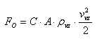 ,
,
where FO is the resistance force [N], C is the resistance coefficient of the object (-), A is the area of the object perpendicular to the wind direction [m2], ρvz is the air density [kg/m3], &vvz is the wind velocity [m/s].
The value of the resistance coefficient is not constant, but depends on the so-called Reynold's number - non-dimensional criterion, expressing the ratio of inertial and viscous
Re = vvz * d / v ,
where d is the characteristic dimension [m] a v is the kinematic viscosity of the air.
If we simplify the antenna (in our case a tribander) to several cylinders, then the characteristic dimension is the diameter and Re equals roughly 104 in normal conditions while the resistance coefficient of the object C is approximately 1.2. By the resistance force acting on the antenna (tube diameter d = 35 mm, length l = 23.6 m, wind velocity vvz = 36 m/s = 130 km/h; air density 1.2 kg/m3) we can determine:
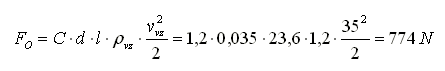 .
.
This force acts as a continuous load on the whole antenna (if we simplify the actual situation on the same velocity profile for the whole surface of the antenna). We can determine the resistance force acting on the mast in a similar way.
The following table illustrates forces calculated for several typical antennas (I apologize to those who can’t find their exact antenna in the table, please just extrapolate).
| Antenna | Wind area [m2] | Force of the wind [N] at speed as [km/h] | ||
| 50 | 130 | 180 | ||
| HF - 3el. tribander ECO | 0,82 | 116 | 765 | 1476 |
| HF - 3el. tribander A3S | 0,40 | 56 | 373 | 720 |
| HF - 3el. tribander TH3JRS | 0,32 | 45 | 299 | 576 |
| HF - 7el. tribander TH7DX | 0,88 | 124 | 821 | 1584 |
| HF - 11el. 5-bander TH11DX | 1,17 | 165 | 1092 | 2106 |
| HF - 10el. LP 10-30m LP1010 | 1,49 | 210 | 1390 | 2682 |
| HF - 5el. for 6m F9FT | 0,13 | 18 | 121 | 234 |
| HF - 5el. for 10m LJ105CA | 0,37 | 52 | 345 | 666 |
| HF - 5el. for 15m LJ155CA | 0,49 | 69 | 457 | 882 |
| HF - 5el. for 20m LJ205CA | 0,84 | 119 | 784 | 1512 |
| HF - 6el. for 20m HD OWA | 1,80 | 254 | 1680 | 3240 |
| HF - vertical 6-20m R6000 | 0,14 | 20 | 131 | 252 |
| HF - vertical 6-40m R8 | 0,24 | 34 | 224 | 432 |
| HF - Inv.V full-size 20-160m | 0,90 | 127 | 840 | 1620 |
| 2m - 9el. 2M9 | 0,12 | 17 | 112 | 216 |
| 2m - 11el. F9FT | 0,18 | 25 | 168 | 324 |
| 2m - 12el. 2M12 | 0,14 | 20 | 131 | 252 |
| 2m - 17el. F9FT | 0,29 | 41 | 271 | 522 |
| 2m - 18el. 2M18XXX | 0,30 | 42 | 280 | 540 |
| 70cm - 18el. 440-18 | 0,08 | 11 | 75 | 144 |
| 70cm - 21el. 440-21ATV | 0,12 | 17 | 112 | 216 |
| 70cm - 38el. 432-13WLA | 0,24 | 34 | 224 | 432 |
| 23cm - 35el. 23CM35EZ | 0,06 | 8 | 56 | 108 |
What can be caused by frost?
The frost, which is a very important element in our calculations, affecting the function (as well as survival) of the antenna, causes
- increase of the surface the wind effects and
- mass gain.
Because I do not have any personal experience with the frost I have consulted this issue with a few friends who have their antennas on a variety of problematic places including those where the frost lasts several months. Their experience indicates that frost on the components adds up to 50-100 % and in extreme cases up to 200 % to their original diameter (the component then increases its diameter). Let’s see how much this increases wind loading.
The previous chapter shows that the resistance force of the wind is directly proportional to the surface of the antenna perpendicular to the wind direction and, therefore, to the diameter of its components. So if the diameter of the components increases 2x, it doubles the wind force. These are very easy calculations - if you wish to design an antenna system for extreme frost, multiply the forces by 3.
The mass issue is more complicated. For its calculation, we need to know not only the thickness of the frost but also its density. Although the density of ice is 917 kg/m3, the density of frost stated in literature and standards is considered 400-500 kg/m3 - let 's calculate preferably 500 kg/m3. Since we are interested in the amount of increase of the mass of the standing antenna, we also need to know the density of the material, which it is made from. This is usually some aluminium alloy whose density is around 2800 kg/m3.
A brief remark about the calculation: for the sake of simplicity, we would again consider an antenna consisting of tubes or rods. The mass of the object m = V * ρ, where V is the volume and ρ the density. The volume of the cylinder is V = π * r2 * l, where r is the radius and l the length. If we substitute the known values we will calculate the original mass and the mass of the frost. This is demonstrated below.
| Design of element /boom | Multiplication of weight with icing: | ||
| 50% | 100% | 200% | |
| Spar (all diameters) | 1,2 | 1,5 | 2,4 |
| Pipe ø 8 mm, wall 1 mm | 1,5 | 2,2 | 4,3 |
| Pipe ø 10 mm, wall 1 mm | 1,6 | 2,5 | 5,0 |
| Pipe ø 14 mm, wall 1 mm | 1,8 | 3,0 | 6,4 |
| Pipe ø 24 mm, wall 1 mm | 2,4 | 4,4 | 9,9 |
| Pipe ø 24 mm, wall 2 mm | 1,7 | 2,8 | 5,7 |
| Pipe ø 30 mm, wall 1 mm | 2,7 | 5,2 | 12,1 |
| Pipe ø 30 mm, wall 2 mm | 1,9 | 3,2 | 6,7 |
| Pipe ø 50 mm, wall 1 mm | 3,8 | 7,8 | 19,2 |
| Pipe ø 50 mm, wall 2 mm | 2,5 | 4,5 | 10,3 |
The facts shown in the table may be shocking for some people. It is not easy to admit that the antenna consisting, for example, of tubes with 24mm in diameter with 1mm wall increases its mass in a 100% frost by 4.4 times! On the other hand, it is necessary to consider that the conditions for creating continuous frost on the entire perimeter of the tube, especially on those with larger diameters, are relatively rare in ordinary QTHs.
As a matter of interest, Wikipedia states the following about frost:
The frost is an atmospheric phenomenon that develops by creating ice crystals on the surface of the object by inflicting the following effects:
• freezing tiny droplets of the air's humidity (clouds, fog etc.) in it's contact with the surface of the ground, object or other subjects at the temperature of 0°C and below;
• precipitation (sublimation) of air's humidity on a sufficiently cold surface of the ground or subjects and that even without the presence of fog or clouds.
The highest probability of frost creation is with contact at a temperature (0 to -4 °C) between the surface of the object and the moist airflow. With temperature below -4 °C the possibility of frost creation decreases and at temperatures below -12 °C frost does not occur or is very weak.
The above data is interesting especially in the consideration of structure & design of the antenna - to what extent the components and the boom should be dimensioned and reinforced to avoid bending. That is again a completely different topic.
Next time, we will focus on guying a real mast, including considerations about its strength and other influencing elements.