Martin Huml, OL5Y/OK1FUA,
In the first part we talked about forces and the issues regarding guying in general; today we will talk about the mast itself. Before I begin I would like to thank for all your feedback, questions and other topics. I am glad that you were interested in the previous article and I will try to keep it that way.
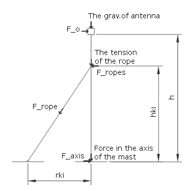
In this sequel we will focus on the most basic version – the tube mast guyed in one level below the antenna. This situation is illustrated under figure 1. To simplify the calculations, we assume that the entire mast is the same tube diameter and has the same properties throughout its length. We will also assume that the wind velocity along the length of the mast is the same (in reality it is lower just above the ground).
When analyzing quantities and properties that affect the behavior of the system we get to this list:
- the total height of the mast, height of the attached rope, distance of the anchor from the mast bottom (to determine forces affecting the system)
- external and internal diameters of the tube (to determine the strength and the weight of the mast)
- physical properties of the material from which the tube is made from: density, elastic modulus, strength limit, proportional limit (to determine the strength and weight of the mast)
- area and weight of the antenna (to determine the wind resistance force)
- coefficient of the resistance of the mast and the antenna (to determine the wind resistance force)
- properties of the environment (air): kinetic viscosity, gravitation acceleration, air density
- wind velocity
Outputs of the calculations we wish to obtain:
- force in the axis of the mast bottom (action on the point of placement of the mast bottom)
- force in the axis of the rope (for the selection of the suitable rope)
However, we will be interested particularly in safety - if the mast will survive and to what degree of safety.
But how to assess and compare safety if it has no unit and its expression in words is quite difficult and above all subjective? We will be probably unable to measure it. Construction sectors use a unit called safety coefficient. It is calculated differently for each type of structure, but its interpretation (sense) is always the same: If it is greater than 1, “there is a theoretical guarantee that the structure will survive”. The recommended minimum value is 1.4. If the safety of the structure involves several factors, the coefficient is calculated for each factor separately and the total safety of the structure is the smallest one of them. In our case, there are two critical factors: the strength of the material of which the mast is made (i.e. the tension in it), and the mast buckling (so the mast will not bend). Our considerations will result in the assessment of the total safety of the system.
From the foregoing, it is clear that there are a large number of quantities that are different for specific situations. Everybody has a different antenna, different mast, different mast height ... For illustration I have chosen several situations, that I find appropriate for demonstration and for which I calculated different outputs. In each case I chose the height of the rope attachment so that the total safety is the greatest. Individual variations are as follows:
- The mast height of 13 m, on which an ECO antenna is placed (3el. tribander for 10/15/20m). This version is calculated for 3 different masts: tube diameter 80 mm with 3 mm thick wall from an average quality duralumin (ver. A), tube from the same material 100/4 mm (B) and steel tube 60/3 mm (C).
- The mast height of 13 m with 11el. antenna for a 2 m band in two versions: average duralumin 60 mm in diameter with a 2 mm thick wall (D) and fiberglass 60 mm in diameter with a 5 mm thick wall (E).
- The last version is a 23 m mast with a bulky antenna TH7DX (7el. tribander for 10/15/20m) again in 2 versions: high quality duralumin 100 mm in diameter with a 10 mm thick wall (F) and steel 100 mm in diameter with a 5 mm thick wall (G).
Other parameters used for calculations are: air density = 1.2 kg/m3, gravity acceleration = 9.82 m/s2, wind velocity = 36 m/s = 130 km/h, coefficient of mast and antenna resistance C = 1.2. The results are shown in table no. 1.
| Quantity | Symbol | A | B | C | D | E | F | G | Unit | |
| 11m duralumin ECO | 11m duralumin ECO |
11m steel ECO |
11m duralumin 11el. 2m | 11m fibreglass11el. 2m | 23m duralumin TH7DX |
23m steelTH7DX |
||||
| mast - tube | ||||||||||
| total height | h | 13 | 13 | 13 | 13 | 13 | 23 | 23 | m | |
| height of rope attachment | h_ki | 12 | 12 | 12 | 11 | 9 | 17 | 20 | m | |
| guy distance | r_ki | 10 | 10 | 10 | 10 | 10 | 15 | 15 | m | |
| external diameter | D_o | 80 | 100 | 60 | 60 | 60 | 100 | 100 | mm | |
| internal diameter | D_i | 74 | 92 | 54 | 56 | 50 | 80 | 90 | mm | |
| mast density | ro_s | 2700 | 2700 | 7850 | 2800 | 1200 | 2800 | 7850 | kg/m3 | |
| elastic modulus | E_s | 60000 | 60000 | 200000 | 60000 | 18000 | 60000 | 200000 | MPa | |
| strength limit | sigma_t | 300 | 300 | 320 | 300 | 220 | 350 | 320 | MPa | |
| proportional limit | sigma_tu | 200 | 200 | 120 | 200 | 200 | 200 | 120 | MPa | |
| rope reaction | F_ropex | 1355 | 1486 | 1223 | 629 | 768 | 2446 | 2079 | N | |
| reaction in mast bottom | F_forces in the axis of the mast | 2023 | 2346 | 2153 | 856 | 858 | 4951 | 5808 | N | |
| reaction in mast bottom perpendicular | F_axis | -381 | -492 | -270 | -267 | -128 | -376 | -743 | N | |
| force in rope axis | F_rope | 2116 | 2321 | 1911 | 934 | 1034 | 3697 | 3466 | N | |
| antenna | ||||||||||
| area of antenna | S_ant | 0,82 | 0,82 | 0,82 | 0,18 | 0,18 | 0,9 | 0,9 | m2 | |
| weight of antenna | m_ant | 15 | 15 | 15 | 3,5 | 3,5 | 40 | 40 | kg | |
| assesing the safety | ||||||||||
| tension in the mast | k_t | 4,01 | 6,21 | 2,86 | 2,37 | 2,14 | 3,16 | 3,34 | ||
| buckling | k_b | 2,47 | 5,84 | 3,62 | 2,01 | 1,89 | 3,27 | 4,75 | ||
| total safety | k | 2,47 | 5,84 | 2,86 | 2,01 | 1,89 | 3,16 | 3,34 | ||
In version (A) I wanted to show that although a relatively thick tube is used the total safety is not as perfect as some might expect based on their experience. This is because the arrangement of the system with a single guy height is definitely not optimal and places high demands on the strength of the mast material. We will talk about other versions next time, but I can disclose that the strength of the system in dual guying is four times greater and even nine times greater in triple guying levels (of course, if they are placed in optimal heights). I have also included version (E) because I have seen similar masts being used by several radio amateurs.
| material | density | elastic modulus | strength limit | proportional limit |
| kg/m3 | MPa | MPa | MPa | |
| duralumin | 2800 | 60000 | 180-450 | x |
| aluminum | 2700 | 60000 | 60-150 | x |
| steel | 7850 | 200000 | 320-835 | 120-290 |
| fiberglass | 1200 | 18000 | 220 | x |
Table no. 2: physical properties of the materials
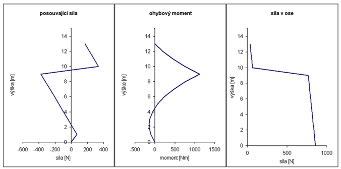
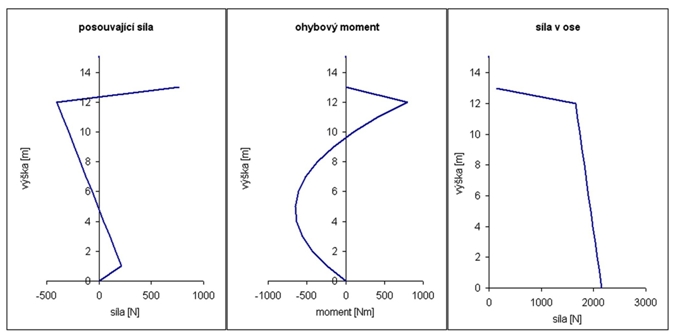
In addition to its own safety system, it is also interesting to look at the distribution of some quantities along the length of the mast. This is shown in figure 2 (for version C) and 3 (E). If the guying height is chosen at a height to maximize safety, then the curve shapes are very similar - that is why I show only 2 typical examples.